Isolate the drive before inspecting notch damage
Only trained, authorized personnel should inspect or service the drive. Observe operation only from a safe position outside the compliant guard, with the guard in place. Before removing the guard, touching, flexing, measuring, cleaning, or adjusting the belt, stop the machine and follow the equipment and site energy-control procedure: isolate every hazardous energy source, apply required locks and tags, control stored energy, and verify de-energization. Control possible reaccumulation of stored energy throughout servicing. This schematic guide does not replace that procedure.
Molded notches describe the belt’s flexing geometry. Cracks, missing rubber, hardening, wear, turnover and separation are observations that require investigation. Preserve the belt and compare measured drive conditions with the exact family’s dimensional, rating, tension, environment and rejection data.
Understand what the notches describe
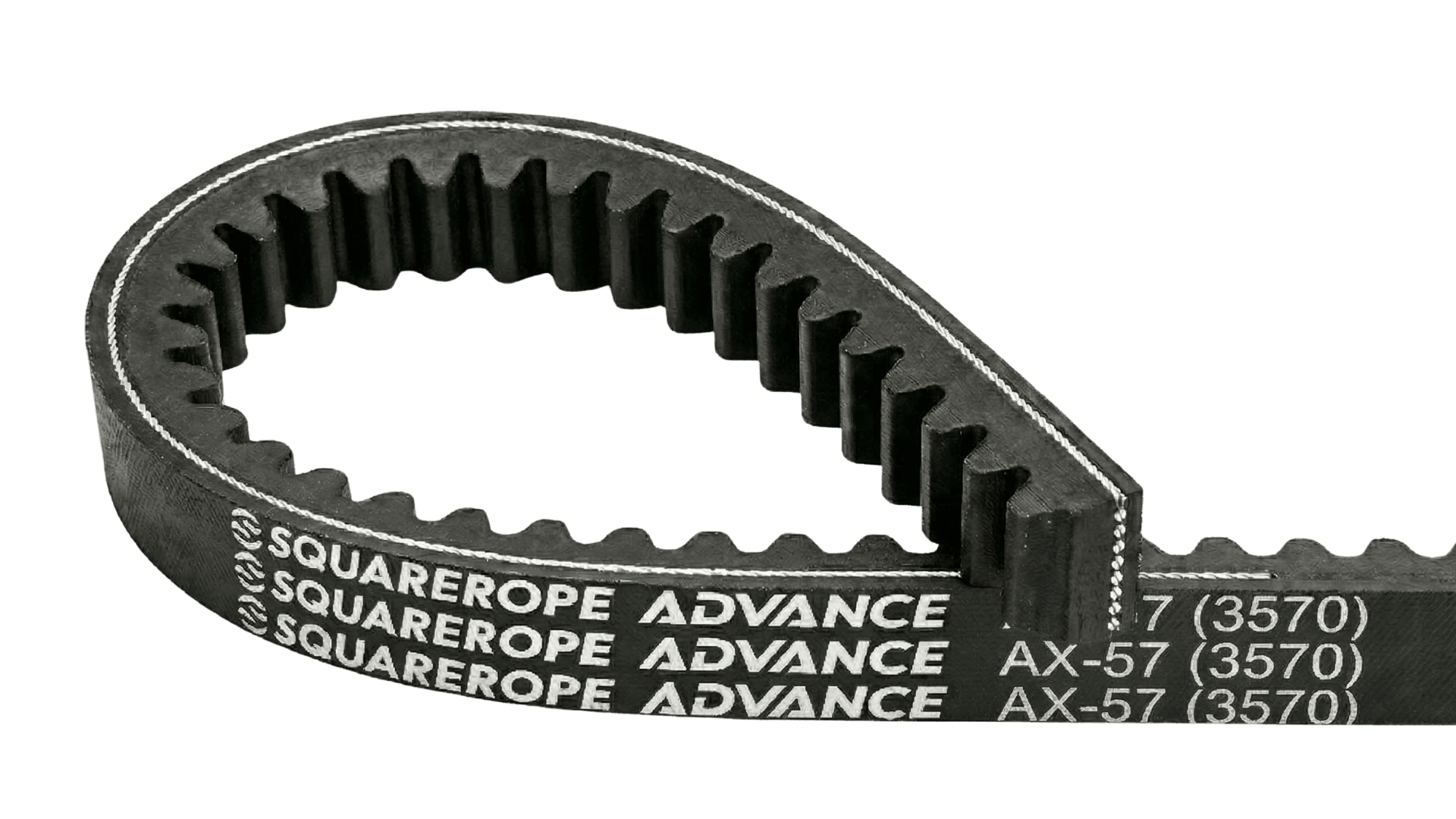
A molded-notch, often called cogged, V-belt has notches formed in the compression section on its inner circumference. The notches reduce bending resistance and increase flexibility. They are not longitudinal cuts in the back, and molded-notch does not mean the same thing as raw-edge; sidewall construction is a separate feature.
Manufacturers may publish smaller minimum pulley diameters, heat-dissipation benefits, or higher ratings for a specific molded-notch family. Apply only that family’s tables. Do not assume a universal percentage, temperature advantage, service life, part-number code, or direction of rotation. Follow a direction arrow only when the exact product carries one or its instructions require it.
Notches run across the belt's inner compression section; they are flexing reliefs, not teeth that mesh with a synchronous pulley. Raw-edge or wrapped describes the working sidewalls; plain or molded-notch describes the underside; single or joined describes assembly. Compound and tensile-member specifications are separate again. Identify each feature from the exact product, rather than treating every raw-edge or 'cogged' belt as the same construction.
For the separate construction features, see V-belt sidewalls, molded notches, assembly and materials before identifying the replacement.
Recognize the construction before judging damage

(1) A molded relief notch opens on the inner compression surface; its root is part of the intended geometry.
(2) Intact material between neighboring notches is a comparison feature, not a remaining-life test.
(3) The upper tensile region is distinct from the inner compression geometry; its position here is schematic.
(4) The working sidewalls are a separate construction feature. This example does not mean every notched belt is raw-edge.
Use damage patterns as evidence, not verdicts
From observation to a testable correction
The candidates are not exhaustive. Appearance alone establishes neither the cause nor a safe remaining life. Use the exact belt family's limits, equipment instructions and rejection criteria.
| Observed evidence | Candidate causes | Distinguishing checks | Conditional action | Verify after correction |
|---|---|---|---|---|
| Rubber missing at a notch or an irregular damaged edge | Damage history, debris or exposure; inspect rather than assigning one cause | Photograph the missing area and nearby intact notches; inspect guards, debris, installation history and exposure | Remove rejected belts from service; address any confirmed interference or contamination before an approved replacement | Inspect the corrected area and replacement after the prescribed guarded test and subsequent isolation |
| Cracks on the inner compression surface or extending from a notch root | Bending conditions, slip or storage/temperature history | Compare sheave and idler diameters on the correct basis with exact family tables; measure tension and review history | Correct the measured departure and apply the manufacturer's rejection and replacement procedure | Record diameter compliance, tension and whether the condition recurs at the specified inspection |
| Sidewall or bottom wear; a glazed, burned or hardened surface | Fit, slip, misalignment, worn grooves or inadequate drive capacity | Identify the contact location; gauge grooves and check alignment, tension, mounts and actual duty | Correct the confirmed fit or drive fault; apply the relevant rejection criteria and approved drive design when deciding component retention or replacement | Record groove, alignment and tension results; observe performance with guards restored |
| Layer separation or exposed cord | Geometry or service damage requires investigation; appearance alone does not identify the event | Preserve the fracture and installation history; check exact diameter limits and drive condition | Keep rejected belts out of service; obtain product-specific guidance for separation or cord damage | Record replacement specification and the corrected geometry before controlled return to service |
| Turnover, loss of tracking or one-sided wear | Alignment, groove fit, tension, unstable mounting or shock/pulsation | Measure offset/angular alignment and tension; inspect shafts, bearings, take-up and recorded duty | Correct the confirmed condition; consider joined construction only when the exact application is approved | Check guarded tracking and stability; stop and isolate before any adjustment |
| Sticky, swollen, softened or flaking surface | Oil or chemical exposure is a candidate, not a material-identification test | Trace leaks and handling/cleaning substances; compare compatibility with the exact product data | Stop the exposure; use approved cleaning and rejection procedures instead of prescribing a universal compound | Confirm the exposure source was removed and record the follow-up condition |
- Candidate causes
- Damage history, debris or exposure; inspect rather than assigning one cause
- Distinguishing checks
- Photograph the missing area and nearby intact notches; inspect guards, debris, installation history and exposure
- Conditional action
- Remove rejected belts from service; address any confirmed interference or contamination before an approved replacement
- Verify after correction
- Inspect the corrected area and replacement after the prescribed guarded test and subsequent isolation
- Candidate causes
- Bending conditions, slip or storage/temperature history
- Distinguishing checks
- Compare sheave and idler diameters on the correct basis with exact family tables; measure tension and review history
- Conditional action
- Correct the measured departure and apply the manufacturer's rejection and replacement procedure
- Verify after correction
- Record diameter compliance, tension and whether the condition recurs at the specified inspection
- Candidate causes
- Fit, slip, misalignment, worn grooves or inadequate drive capacity
- Distinguishing checks
- Identify the contact location; gauge grooves and check alignment, tension, mounts and actual duty
- Conditional action
- Correct the confirmed fit or drive fault; apply the relevant rejection criteria and approved drive design when deciding component retention or replacement
- Verify after correction
- Record groove, alignment and tension results; observe performance with guards restored
- Candidate causes
- Geometry or service damage requires investigation; appearance alone does not identify the event
- Distinguishing checks
- Preserve the fracture and installation history; check exact diameter limits and drive condition
- Conditional action
- Keep rejected belts out of service; obtain product-specific guidance for separation or cord damage
- Verify after correction
- Record replacement specification and the corrected geometry before controlled return to service
- Candidate causes
- Alignment, groove fit, tension, unstable mounting or shock/pulsation
- Distinguishing checks
- Measure offset/angular alignment and tension; inspect shafts, bearings, take-up and recorded duty
- Conditional action
- Correct the confirmed condition; consider joined construction only when the exact application is approved
- Verify after correction
- Check guarded tracking and stability; stop and isolate before any adjustment
- Candidate causes
- Oil or chemical exposure is a candidate, not a material-identification test
- Distinguishing checks
- Trace leaks and handling/cleaning substances; compare compatibility with the exact product data
- Conditional action
- Stop the exposure; use approved cleaning and rejection procedures instead of prescribing a universal compound
- Verify after correction
- Confirm the exposure source was removed and record the follow-up condition
Source: Original SQUAREROPE diagnostic synthesis; product limits must be checked for the selected belt and drive.
Separate a crack from missing material

(1) A narrow discontinuity extending into the rubber is a crack observation; preserve its location and extent.
(2) An adjacent intact notch helps compare the feature against the exact product geometry.
(3) An irregular void represents missing material; record nearby impact, debris, installation and exposure evidence.
(4) The dashed comparison outline is illustrative. It supplies no rejection depth, rate or service-life limit.
Verify pulley and idler geometry
Check the small sheave and every inside or backside idler against the exact product-family data. Assess diameter on its specified basis together with profile, construction, speed, power, idler contact side and placement, and duty. Being at a published minimum alone neither establishes suitability nor proves a cause of damage.
Identify the diameter basis before comparing values. Do not substitute outside diameter for datum or pitch diameter unless the manufacturer supplies the conversion. Inspect groove profile, wear, damage, runout and debris with the correct gauge. Apply the manufacturer's rejection criteria and the approved drive design when deciding whether to retain or replace a sheave.
Measure tension, fit, alignment, and load
Measure tension with a calibrated instrument using the method and target specified for the exact belt and drive. Both insufficient and excessive tension can damage a drive, but notch closure is not a universal tension diagnostic. Do not flex a removed belt sharply to open cracks or kink it. Follow the exact maker's handling and storage bend limits; do not infer them from an operating sheave table alone.
Check angular and offset alignment, center-distance stability, bearings, shafts, mounts and take-up. Then verify actual power or torque, speeds, starting method, service factor, arc of contact, belt length and corrected family rating. Do not select a different profile from damage appearance alone.
Record where the belt is wearing

(1) Record which working sidewall is affected and whether the wear is one-sided.
(2) Record bottom-surface wear separately; inspect fit, grooves and debris before attributing bottom contact.
(3) The dashed contour is a drawing reference only. Use the exact manufacturer's gauge and criteria, not this outline, for assessment.
Check temperature, contamination, storage, and materials
General hardening or cracking can be associated with operation outside the belt’s temperature range, while sticky, swollen or flaking surfaces can indicate excessive oil or chemical contamination. These are candidates to confirm against the exact product data, not reasons to prescribe a material by name.
Eliminate leaks and debris, and follow the equipment and exact belt-maker instructions for cleaning and surface treatments. Do not use belt dressing to mask slip or damage. Check storage for heat, sunlight, ozone sources, chemicals, distortion and bends outside the specified handling limits. Compound, chemical, oil, temperature, ozone, weather and static properties must be checked for the exact series.
Evaluate shock, vibration, and joined construction separately
If shock, pulsation or vibration accompanies turnover or loss of groove tracking, record the duty and drive condition before considering a different assembly. Joined construction may be specified for an approved application, but its presence does not establish the cause or guarantee that the damage will stop.
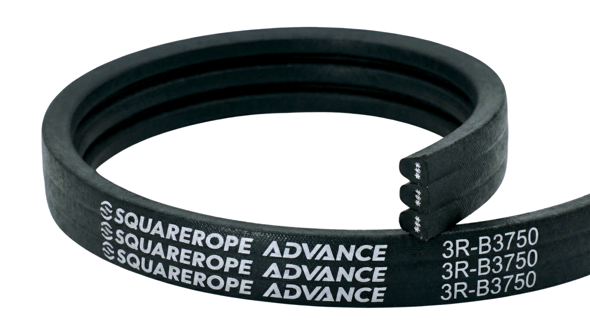
Confirm the joined belt’s exact rating, number and spacing of grooves, pulley compatibility, minimum diameters, tension procedure and service factor. If the manufacturer does not approve joined construction for the drive, do not treat it as a generic upgrade.
Keep rejected belts out of service and verify corrective work
Use the exact manufacturer's rejection criteria to decide whether the belt can remain in service. Do not operate a rejected belt while waiting to identify the root cause. Preserve the removed belt and correct the confirmed drive fault before returning the drive with its replacement belt to service. Follow the sequence below; isolate before collecting evidence that requires access to the drive.
- Apply the site energy-control procedure and verify de-energization before guard removal or contact.
- Photograph and label the installed belt or complete set, every damaged area, sheaves, idlers, guard, mounts and contamination before cleaning.
- Confirm the full belt designation, product family, matched-set information and whether the exact instructions specify a direction of rotation.
- With the drive isolated, measure diameters, tension, alignment, runout and center distance; gauge every groove and inspect bearings, shafts and take-up. Obtain operating speed and load data from existing records or earlier safe observation with guards in place; these are not contact measurements on a running drive.
- Correct the verified drive-level cause and replace each sheave or component that is outside its manufacturer limit.
- Install the exact replacement or complete compatible matched set by hand with slack, without prying, rolling, kinking or forcing.
- Set exact tension, restore and secure the guard, perform a controlled test, and stop and isolate again before adjustment. Follow the exact run-in rule.
Keep the inspection sequence intact

(1) Stop; isolate all hazardous energy, lock or tag as required, control stored energy and reaccumulation, and verify isolation before guard removal or contact.
(2) Preserve photographs and damage locations; identify the exact belt family, construction and service history before cleaning or replacement.
(3) Check dimensions on the specified basis, tension method/target, grooves, alignment, duty and exposure against exact data.
(4) Keep rejected belts out of service; correct confirmed faults and install an approved replacement. Restore guards for the controlled test; stop and re-isolate before adjustment.
Build a repeatable inspection record
Keep these values for recurrence analysis:
- Manufacturer, product family, complete designation, construction and matched-set data.
- Damage location on the top, sidewall, inner compression surface, notch root, cord line and fracture face.
- Small-sheave and idler diameters with their measurement basis and applicable manufacturer minimums.
- Measured tension, instrument, target source, alignment, runout, groove gauge and center-distance results.
- Power or torque, speeds, start method, service factor, daily hours, shock, pulsation and vibration.
- Temperature and exposure to oil, grease, coolant, chemicals, water, dust, debris, ozone and sunlight.
- Installation, storage, maintenance, run-in and previous replacement history.
- Confirmed cause, corrective action, replacement specification and guarded test result.
Use the V-belt preventive-maintenance and inspection workflow to organize safe checks, records and return-to-service verification.
The notches explain how the belt flexes; they do not explain every failure. A reliable diagnosis connects the observed damage to measured geometry, drive condition, duty and exact product limits before the replacement is approved.
Key Takeaway
What causes cracks or missing rubber on a cogged V-belt?
Appearance alone cannot establish a single cause. Check exact sheave and idler requirements, tension, fit and drive condition, installation and storage history, duty and exposure against the belt-maker's data before confirming the cause.
For a drive-specific review, contact SQUAREROPE with the full belt designation, photographs, drive measurements and service history.