Collect drive data safely
In covered US industrial operations under OSHA 29 CFR 1910.147 (and applicable site safety procedures and local regulations elsewhere), stop the machine, isolate and lock out or tag out all hazardous energy sources, control stored energy, and verify de-energization before servicing or inspecting drive components. Observe operation only from behind compliant physical guards under OSHA 29 CFR 1910.219.
An industrial V-belt cannot be specified by equipment name, nominal horsepower, or top width alone. A defensible dimensional specification connects the exact profile family and drive geometry to standardized datum systems, verified sheave grooves, and manufacturer-specific length conventions.
![Two-panel technical diagram showing numbered observation callouts for V-belt top width [1.1], datum width reference [1.2], belt height [1.3], and drive length reference paths for outside length [2.1], datum length [2.2], inside length [2.3], and shaft center distance [2.4].](https://cdn.sanity.io/images/g3z6082m/production/107d62d3be81c16f0f3cb8f855e79ec59213c0ff-1200x980.svg?w=3840&q=80&fit=max&auto=format)
Key diagram callouts and reference paths:
- 1.1 — Top-width observation location
- 1.2 — Conceptual datum-width reference governed by the applicable profile standard. It characterizes the matching sheave groove; the standard, not the drawn line or the cord position, sets its level, and a pitch or effective reference in another length system can sit at a different level.
- 1.3 — Belt-height observation
- 2.1 — Outside-length reference concept
- 2.2 — Datum-length reference concept: the length at the datum-diameter level of the measuring sheaves, under the tension and conditions the applicable system specifies
- 2.3 — Inside-length reference concept
- 2.4 — Shaft center distance
Establish the drive dimensional basis before ordering
Record the driver and driven equipment, operating shaft speeds, power transmission requirements, and physical center distance before removing an existing belt. Equipment names alone do not determine a profile standard or dimensional system.
Record small and large sheave datum or pitch diameters, speed ratio, center distance, take-up travel, shaft condition, alignment, and guarding envelope. A replacement belt that matches an old physical loop can still fail if the sheave groove standard or dimensional system is mismatched.
Separate the dimensional and profile decisions
Independent specification decisions
Each row is a separate decision. Do not infer one property from another.
| Decision | Common options | Evidence required |
|---|---|---|
| Profile system | Classical, narrow-wedge, or another maker-specific family | Current selection diagram, rating table, compatible sheave standard |
| Sidewall or cover | Wrapped or raw-edge | Exact family construction, environment, grip, and rating data |
| Underside geometry | Smooth or molded-notch | Exact minimum diameter, speed, flexibility, and rating data |
| Assembly | Single, matched separate set, or joined/banded | Duty, groove count and spacing, pulley compatibility, maker approval |
| Materials | Body compound, tensile cord, cover or back fabric | Exact temperature, oil, chemical, weather, static, and regulatory documentation |
| Length system | Datum, effective, pitch, inside, or outside designation | Manufacturer marking rules and the corresponding standard length |
- Common options
- Classical, narrow-wedge, or another maker-specific family
- Evidence required
- Current selection diagram, rating table, compatible sheave standard
- Common options
- Wrapped or raw-edge
- Evidence required
- Exact family construction, environment, grip, and rating data
- Common options
- Smooth or molded-notch
- Evidence required
- Exact minimum diameter, speed, flexibility, and rating data
- Common options
- Single, matched separate set, or joined/banded
- Evidence required
- Duty, groove count and spacing, pulley compatibility, maker approval
- Common options
- Body compound, tensile cord, cover or back fabric
- Evidence required
- Exact temperature, oil, chemical, weather, static, and regulatory documentation
- Common options
- Datum, effective, pitch, inside, or outside designation
- Evidence required
- Manufacturer marking rules and the corresponding standard length
Source: SQUAREROPE Technical Team specification decision framework
Distinguish classical and narrow-wedge profile systems
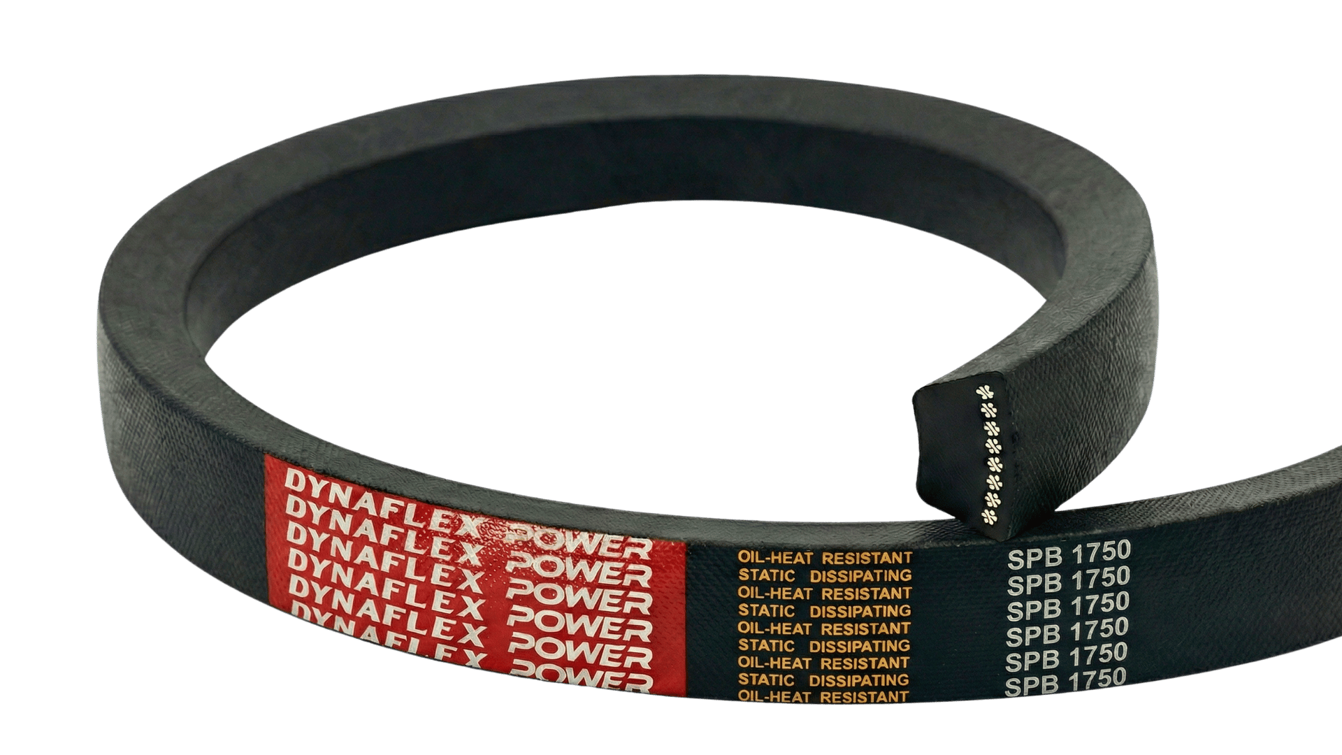
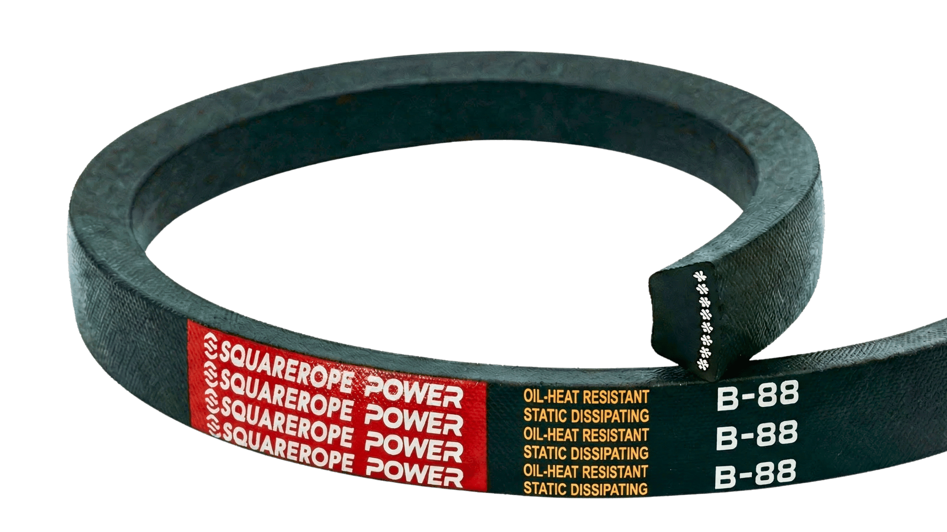
Classical (Y, Z, A, B, C, D, E) and metric narrow-wedge (SPZ, SPA, SPB, SPC) profiles use different dimensional systems and matching sheaves. Narrow-wedge profiles may offer higher power density for a given envelope depending on the exact product family and drive conditions, but profiles such as SPA and A remain separate systems and are not interchangeable merely because their nominal top widths appear close.
Unit arithmetic converts dimensions (1 in = 25.4 mm) but does not establish profile, sheave, or product equivalence across regional or manufacturer standards. ISO 4184:2025 specifies lengths in the datum system for classical and narrow profiles, while ISO 4183:2026 specifies corresponding grooved pulleys; application power ratings and drive calculations remain governed by the applicable manufacturer or OEM design manual.
Understand cross-section geometry, assembly, and materials
Wrapped and raw-edge describe the driving sidewalls; smooth and molded-notch describe the inner compression surface. Cross-section variables include top width and nominal height; datum width is a system-defined reference for the matching sheave groove, not a fixed line on the belt. Worn-belt measurements are physical clues only and do not establish nominal design specifications.
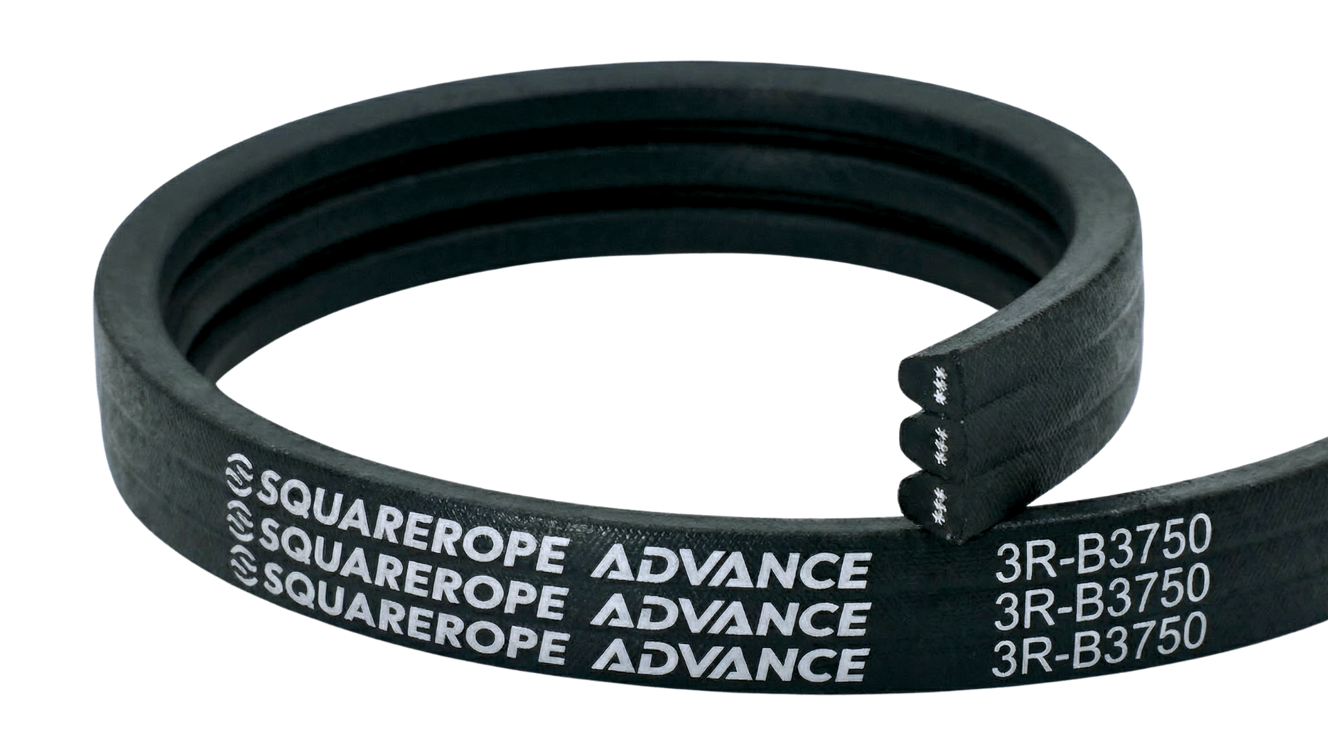
Single versus joined or banded assembly is a separate operational decision; banded belts may help resist lateral whip or turnover under pulsating loads. Compound materials, temperature limits, oil resistance, and static conductivity require verification against applicable product series data sheets rather than assumption from profile geometry.
Verify groove compatibility and manufacturer length boundaries
Drive rating, service factor calculation, and power capacity require the applicable manufacturer design procedure. Article 14 establishes the dimensional and length foundation, while power capacity calculations are governed by the applicable manufacturer design method.
Verify center take-up travel for standard length fit, minimum recommended sheave diameters, maximum belt speed, and groove wear before installation. Calibrated tensioning, hardware torque, and retension schedules must follow the belt manufacturer instructions.
Step-by-step dimensional replacement procedure
Establish the dimensional replacement in this structured order:
- Freeze and record existing belt markings, manufacturer, product family, profile designation, length code, and sheave markings before removal.
- Establish the exact profile and family system from drive geometry and operational speed requirements before replacement sizing.
- After verifying de-energization and safe isolation, measure sheave datum diameters, groove profile and count, center distance, and take-up adjustment travel.
- Document temperature, oil, chemical, debris, and static exposure boundaries affecting belt series selection.
- Record top width, belt height, and circumference observations; explicitly treat worn-belt measurements as physical clues rather than nominal design specifications.
- Identify whether the drive uses datum, effective, pitch, inside, or outside length; verify corresponding standard length and compatible grooved sheave standards.
- Confirm supplier-specific manufacturing length tolerances, matching limits, and OEM application constraints before final order release.
- Obtain manufacturer or OEM confirmation when the profile standard, length system, or groove compatibility is uncertain.
If physical belt markings are degraded, damaged, or unreadable, refer to the physical V-belt identification guide to establish the initial cross-section clues and preserve physical evidence before sizing replacement lengths.
Dimensional verification checklist before order release
The dimensional replacement record should verify:
- Manufacturer, exact product family, full profile designation, nominal length value, and governing length system (datum, effective, pitch, inside, outside).
- Driver and driven equipment, operating speeds, and power transmission context.
- Sheave profile standard, datum or pitch diameters, groove count and condition, center distance, and take-up adjustment range.
- Confirmation that profile identity and compatibility are verified against applicable standards and maker documentation, not inferred from unit arithmetic (1 in = 25.4 mm).
- Operating temperature limits and environmental exposure boundaries (oil, chemicals, outdoor, static) documented from series specifications.
- Installation clearance, center adjustment travel, and manufacturer tensioning method reference.
- Complete matched-set replacement requirement for multiple-belt drives; never mix used and new belts or combine belts from different manufacturers.
- Machine isolation, guarding compliance, and safe servicing authorization in accordance with site safety procedures.
Industrial reliability comes from a traceable dimensional specification, not from a generic profile hierarchy. Separate every design decision, verify exact length and sheave systems, and retain measurements needed to repeat the result.
Key Takeaway
How do you identify the correct industrial V-belt replacement dimensions?
To identify the correct dimensional replacement basis, preserve markings, establish the exact profile family, record safely obtained width/height/length observations, identify the governing length system, verify compatible sheaves, and confirm the exact supplier/OEM tolerances.
Need help documenting an industrial drive? Review the V-Belt range and SP Power Belt, or contact SQUAREROPE with the complete drive record.