V-belt construction affects sheave engagement, bending resistance, and environmental response; wrapped, raw-edge, molded-notch, and joined describe separate physical features that can coexist rather than mutually exclusive belt categories.
Four Decisions, Not Three Types
Identify each construction axis separately before comparing products:
- Sidewall and cover: wrapped versus raw-edge.
- Underside geometry: plain versus molded-notch.
- Assembly: single versus joined.
- Materials: body compound, tensile cords, and fabrics.
![Four-panel engineering diagram showing V-belt construction axes with numbered callouts: wrapped [1.1] versus raw-edge [1.2] sidewalls, plain [2.1] versus molded-notch [2.2] transverse flexing reliefs (non-synchronous), single [3.1] versus joined [3.2] assembly with continuous top tie band, and material cross-section layers including top fabric [4.1], load-carrying tensile cords [4.2], cushion rubber [4.3], and compression compound [4.4].](https://cdn.sanity.io/images/g3z6082m/production/e11b7f36a449260cd743fd6b03b80fbe5fe23ccd-1200x980.svg?w=3840&q=80&fit=max&auto=format)
Diagram callout key across the four orthogonal construction axes:
- 1.1 — Wrapped or covered working sidewalls (protective textile jacket)
- 1.2 — Raw-edge working sidewalls (exposed compound direct flank contact)
- 2.1 — Plain or smooth underside compression geometry
- 2.2 — Molded-notch transverse flex relief (non-synchronous, not timing teeth)
- 3.1 — Single V-belt strand
- 3.2 — Joined or banded assembly with continuous top tie band
- 4.1 — Top fabric or tension backing layer
- 4.2 — Load-carrying tensile cords
- 4.3 — Cushion or adhesion rubber layer
- 4.4 — Compression elastomer compound layer
Wrapped or Covered Sidewalls
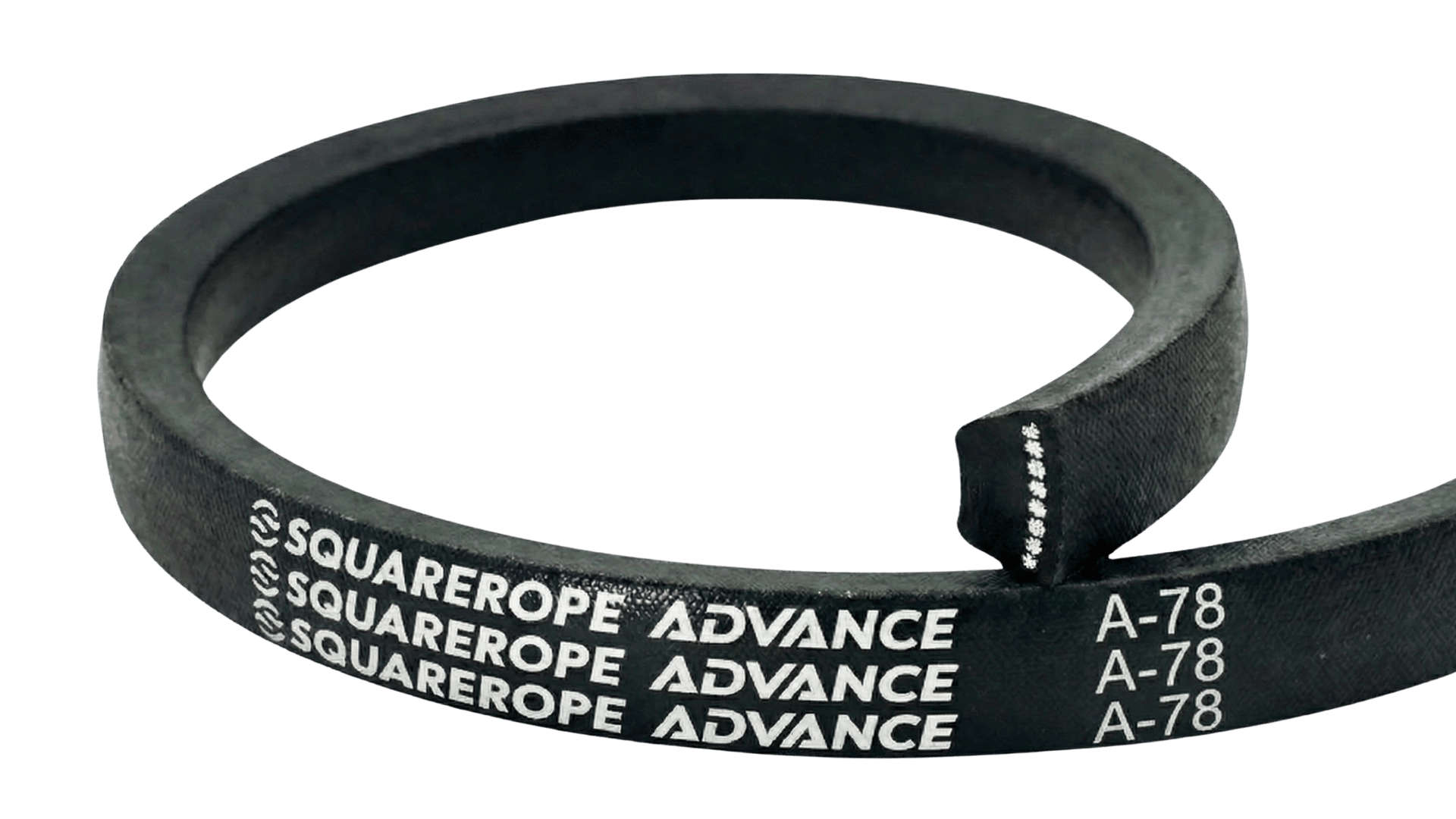
A wrapped V-belt has a textile fabric cover enclosing the entire belt cross-section and working sidewalls, providing an external protective barrier between the core compound and sheave groove flanks.
Cover fabrics, rubber compounds, friction coefficients, and environmental tolerances vary by product series; specify a wrapped belt for abrasive or contaminated duty only when recommended by the manufacturer for the specific application.
Raw-Edge Sidewalls
Raw-edge describes uncovered working sidewalls where formulated elastomer or fiber-loaded compound contacts sheave flanks directly, while load-carrying tensile cords remain embedded and protected within the core.
Raw-edge construction does not mean fabric is entirely absent; many raw-edge belts retain fabric on the top or backing layer. Direct flank contact can improve frictional grip, but power ratings, efficiency, thermal behavior, and service life must be verified from exact manufacturer series rating tables.
Molded-Notch or Cogged Base
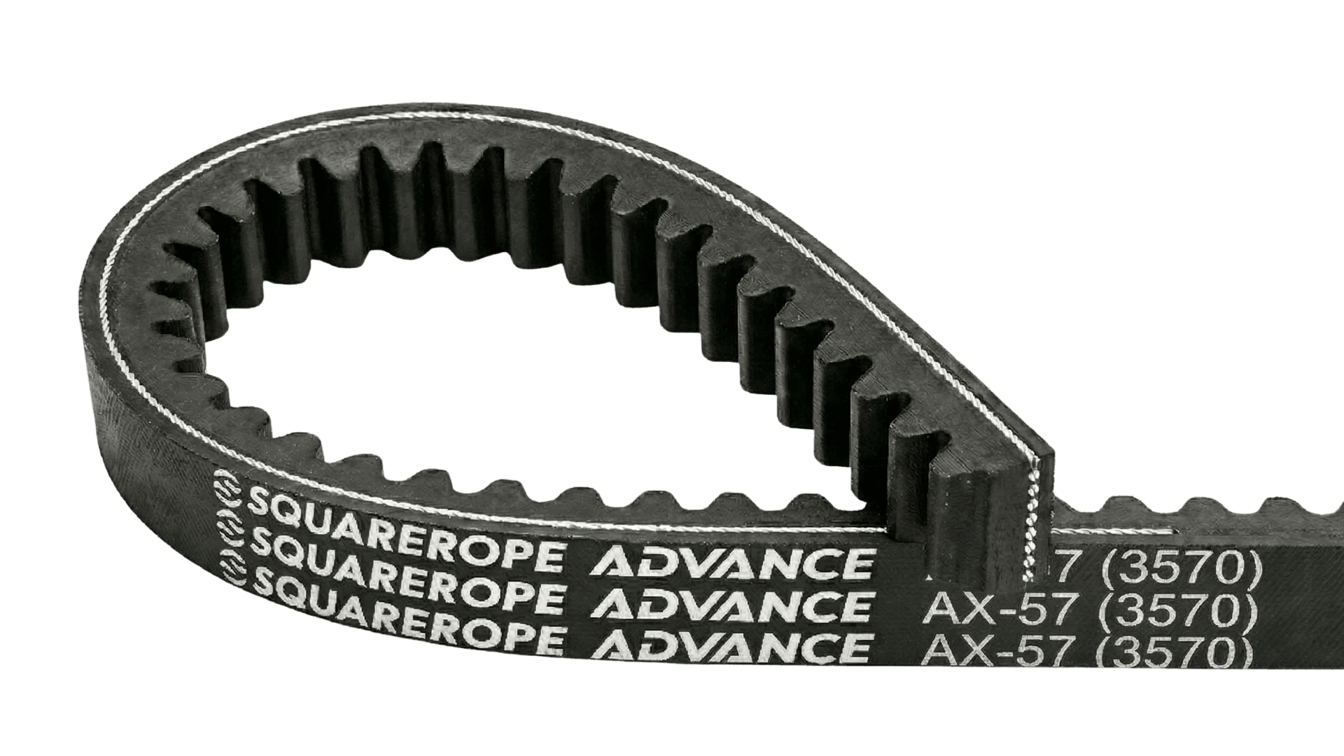
A molded-notch belt features transverse relief notches molded into the inner compression section during manufacturing, reducing bending resistance and increasing flexing capability over pulleys.
Molded-notch construction can permit smaller minimum sheave diameters when permitted by manufacturer engineering tables; heat dissipation effects vary by design and must be confirmed from exact product series data.
Part numbering letters and catalog designation codes are manufacturer-specific conventions rather than universal standardization rules; verify exact markings against manufacturer catalogs rather than assuming cross-brand letter equivalents.
Do not confuse molded notches with synchronous teeth
Do not confuse molded notches with synchronous teeth: molded notches provide bending flexibility and do not mesh with sheave grooves for timing; V-belts transmit power purely through friction along the wedging sidewalls.
When belt markings are worn, ambiguous, or need physical verification, follow the physical V-belt identification and measurement guide to preserve drive evidence and determine the exact replacement cross-section.
Joined or Banded Assembly
A joined (banded) belt connects two or more individual V-belt strands with a vulcanized top tie band into a single integrated unit, where increased lateral rigidity helps resist belt whip, turnover tendencies, and groove disengagement under pulsating or shock loads.
Joined belts are specified for drives with pulsating torque, shock loads, or vibration that cause single-belt whip or turnover; follow manufacturer joined-belt design tables and installation guides, and do not infer overload capability from sidewall form alone.
Construction Terms at a Glance
V-Belt Construction Comparison
| Comparison | Wrapped or covered | Raw-edge | Molded-notch | Joined or banded |
|---|---|---|---|---|
| Feature described | Textile fabric cover enclosing working sidewalls | Uncovered compound contacting sheave flanks directly | Transverse relief notches molded into inner compression section | Multiple strands connected by a vulcanized top tie band |
| Typical selection reason | Manufacturer-approved cover protection in harsh or abrasive duty | Verified series grip, efficiency, or rating advantage | Flexing in compact drive layouts with approved small sheaves | Controlling belt whip, turnover, or vibration under pulsating loads |
| Evidence to verify | Cover material, friction characteristics, environment, and series power rating | Series power rating, allowable speed, temperature limits, and guarding | Minimum sheave diameter, allowable speed, and power curves | Joined-belt rating, sheave groove spacing, tensioning, and installation data |
| Do not assume | Guaranteed longer life or sacrificial overload slip | Universal power or efficiency percentage increase | Universal cooling, noise reduction, or service-life extension | That all shock-loaded drives require the same joined assembly |
- Wrapped or covered
- Textile fabric cover enclosing working sidewalls
- Raw-edge
- Uncovered compound contacting sheave flanks directly
- Molded-notch
- Transverse relief notches molded into inner compression section
- Joined or banded
- Multiple strands connected by a vulcanized top tie band
- Wrapped or covered
- Manufacturer-approved cover protection in harsh or abrasive duty
- Raw-edge
- Verified series grip, efficiency, or rating advantage
- Molded-notch
- Flexing in compact drive layouts with approved small sheaves
- Joined or banded
- Controlling belt whip, turnover, or vibration under pulsating loads
- Wrapped or covered
- Cover material, friction characteristics, environment, and series power rating
- Raw-edge
- Series power rating, allowable speed, temperature limits, and guarding
- Molded-notch
- Minimum sheave diameter, allowable speed, and power curves
- Joined or banded
- Joined-belt rating, sheave groove spacing, tensioning, and installation data
- Wrapped or covered
- Guaranteed longer life or sacrificial overload slip
- Raw-edge
- Universal power or efficiency percentage increase
- Molded-notch
- Universal cooling, noise reduction, or service-life extension
- Joined or banded
- That all shock-loaded drives require the same joined assembly
Source: SQUAREROPE Technical Team
Before ordering or modifying drive components, consult the industrial V-belt dimensions and datum length reference to verify cross-section profiles, standard length systems, and sheave groove compatibility.
Compound, Environment, and Static Requirements
Construction geometry and material specifications are separate engineering decisions; wrapped, raw-edge, molded-notch, or joined designations do not specify body polymer compound, tensile cord chemistry, oil resistance, chemical resistance, operating temperature range, ozone resistance, or service life.
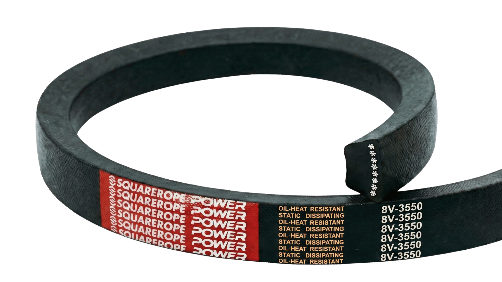
If antistatic conductivity is required, obtain the declaration for the exact belt series and verify the complete grounded drive path; ISO 1813 specifies laboratory test methods and electrical resistance limits for antistatic V-belts and joined belts, but is not a blanket supplier or product certification. Labeling a belt “oil resistant” indicates resistance to occasional incidental exposure and does not mean continuous liquid immersion or compatibility with all industrial solvents and synthetic lubricants.
Selection Checklist
Before changing construction or ordering a replacement:
- Identify all four axes independently: sidewall cover form, underside compression geometry, single versus joined assembly, and material formulation.
- Confirm that the wrapped series is manufacturer-recommended for the abrasive or harsh operating environment.
- Check the raw-edge series power rating table, grip or efficiency evidence, operating temperature limits, and guarding requirements.
- Check the molded-notch series minimum sheave diameter, speed limits, and power curves.
- Confirm that the joined series is specified for the belt whip, pulsation, shock, or vibration characteristics in the drive.
- Confirm belt profile and length basis (refer to Article 14 for dimensional standards and Article 01 for marking interpretation), sheave groove condition, and drive alignment.
- Verify environmental and chemical compatibility along with any required antistatic conductivity declarations under ISO 1813.
- Follow the manufacturer’s exact tensioning and retensioning procedures for the specific belt construction and drive geometry.
- In multi-belt drives, replace the entire set together with matched belts from the same manufacturer; never mix new and worn belts or different brands.
Choose V-belt construction based on manufacturer engineering tables and actual drive operating requirements rather than generic marketing claims about wrapped, raw-edge, or cogged belts.
Key Takeaway
What is the difference between wrapped, raw-edge, molded-notch, and joined V-belts?
Wrapped and raw-edge describe sidewall form, molded-notch describes underside geometry, and joined describes multiple strands connected by a tie band. Because these features can coexist, verify the exact series, rating, minimum sheave diameter, materials, and application requirements.
Need help selecting the correct construction? Review our V-Belt and Cogged V-Belt product pages, or contact SQUAREROPE for application engineering support.